DPR Git Pages Home — Artifacts Index
Artifact/Template: Deployment Diagram
a.k.a. Operational View, Physical View
A deployment diagram depicts a runtime configuration of a software-intensive system, consisting of physical elements such as compute nodes, storage units, and network connections. It may include information about the placement of application parts as well as systems management devices.
Motivation (Addressed Information Need)
The C4 model page on Wikipedia defines “A deployment diagram allows you to illustrate how software systems and/or containers in the static model are mapped to infrastructure.” The static model is expressed in instances of Overview Diagrams as well as Component Diagrams.
Usage (Produced and Consumed When)
This artifact is required for any production environment, including cloud deployments. Its usage scenarios include:
- Project management, logical-physical design interlock
- Capacity planning, hosting decision making (on-premise? in the cloud?)
- Preparation of hardware procurement
- Quality assurance reviews w.r.t. runtime characteristics (performance, availability, scalability)
- Preparation and execution of system operations, including systems management activities.
Notation(s)
Many custom notations and Domain-Specific Languages (DSLs) for topology modeling and configuration management exist today, for instance, coming from cloud providers and CI/CD vendors. Oftentimes, informal rich pictures are used that visualize the following model elements and their relationships:
- Network zones
- Compute and storage nodes (both virtual and physical ones)
- Deployment units, installable software
- Infrastructure components such as firewalls, gateways, caches, authenticating proxies, directories, load balancers, management agents and management clients, log archives and credentials vaults, database replicators
- Network connections and other dependencies between these diagram elements
UML is a valid and popular choice and has a dedicated diagram type of this name, deployment diagram.
Example(s)
The deployment units and physical tiers in an order management scenario in telecommunications may look as follows (in a hot standby or load-balancing configuration):
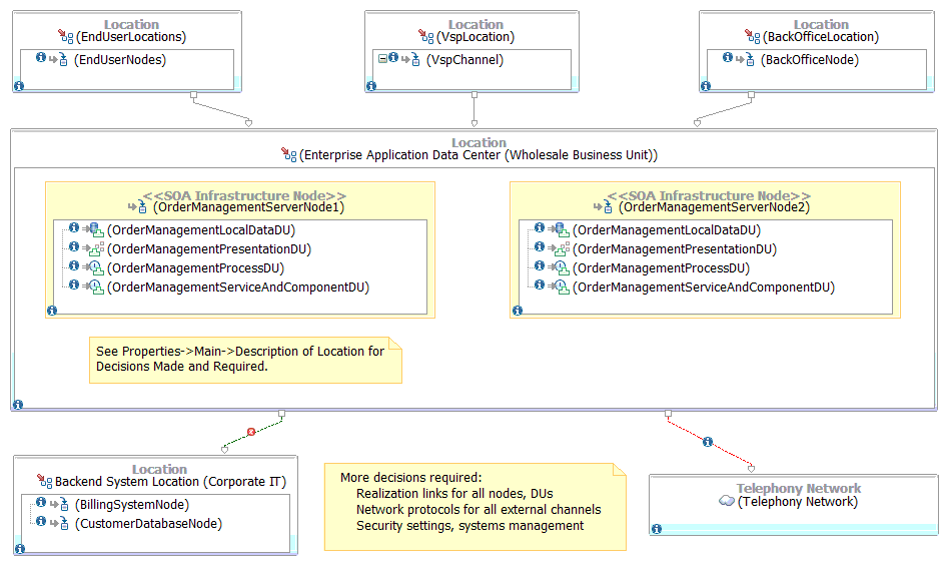
The locations in this example contain one or more nodes. The mid-tier, for instance, is called Enterprise Application Data Center in this example. Two nodes are configured redundantly (in terms of application deployment units, DUs) to support load balancing and standby/failover capabilities (to improve reliability and availability). A UML note comments on architectural decisions still required (while decisions already made manifest themselves in the diagram).
Tools
Common tool choices include:
- Any drawing tool, possibly supported by domain-specific templates, icon collections, stencil libraries, and so on.
- Physical and online whiteboards (in support of agile modeling)
- UML tools with Sparx Enterprise Architect being one example
- C4-enabled tools such as Structurizr
Infrastructure architecture and system management are fields and competence areas in their own right; therefore, many practices, notations, and tools exist that are out of our scope here.
Hints and Pitfalls to Avoid (Common Pitfalls)
- Do not start the operational design too late, but develop component diagram and deployment diagram hand in hand.
- Model iteratively, starting on a conceptual, platform- and technology-independent level to promote qualities such as design portability and cloud agnosticism.
- Do not forget to address cross-cutting concerns such as logging and monitoring. Consult the security guidelines for the target platform to ensure that the requirements of the CIA triad and other security requirements can be satisfied.
- Follow the general modeling hints and guidelines from Gernot Starke (in German for the time being), Simon Brown, and others to ensure readability and maintainability.
- Keep the diagram current as the design evolves, and the hosted system advances throughout its lifecycle.
Origins and Signs of Use
Deployment diagrams have a long history:
- IBM ADS and System Integration/Global Services Method
- Unified Modeling Language (UML)
- C4 Model, as a later addition (not part of the original four C).
Also see the book chapter “Architectural Knowledge in an SOA Infrastructure Reference Architecture” for motivation and usage context (PDF).
Related Artifacts and Practices (incl. Alternatives)
DPR activities:
Artifact types and notations:
- Architecture Overview Diagram
- Component Diagram
- C4 Model for visualizing software architecture by Simon Brown
- Unified Modeling Language (UML) deployment diagrams
More Information
- The notion of operational models on different levels of refinement (conceptual, specified, physical) is explained in “Architectural Knowledge in an SOA Infrastructure Reference Architecture”.
- Philippe Kruchten introduces the 4+1 model in “The 4+1 View Model of Architecture”.
- Sparx Systems provides a UML Tutorial.
- arc42 has a deployment view and a runtime view.
Data Provenance
title: "Design Practice Repository (DPR): Deployment Diagram"
author: Olaf Zimmermann (ZIO)
date: "01, 31, 2023"
copyright: Olaf Zimmermann, 2023 (unless noted otherwise). All rights reserved.
license: Creative Commons Attribution 4.0 International License